
Modeling inflatable panels
Inflatable structures

BEAM inflatable module expansion (NASA)
Advantages
- very material-saving
- lightweight
- movable
- reusable
- easy to repair (patching)
- adjustable stiffness
Target industries
So far, inflatable plates are mainly used in sports equipment such as stand up paddles (SUP) and air tracks (tumbling mats). But NASA and other space agencies are interested in inflatable habitats ([1], [2]) and pressurized panels may become a key component of space exploration.
Other potential applications involve inflatable movie screens, inflatable plane wings, air mattresses and air tunnels.
Perspectives
Our hope is that our model will help engineers design load bearing inflatable buildings on Earth or in space.
Plate theory
Why a plate model?
Our goal is to obtain 2D equations that describe our 3D system. Since the geometry of the panel is closer to a 2D body than it is from a 3D one, it seems reasonable to focus our efforts on the two in-plane dimensions.
Kinematics
A plate is modeled as a plane onto which a "field" of fibers is attached. Every point $$\vec P$$ of the mid-surface is pierced by a straight line called the normal fiber (it is only normal in the initial configuration). The fiber is guided by the vector $$\vec a_3$$.
We work with the Mindlin–Reissner kinematics assumption: \[ \vec a_3 = \tens R \cdot \vec e_3 \] with $$\tens R = \tens R (\vec P_0,t)$$ a rotation tensor field. This means that the fibers behave like rigid bodies: they may rotate but not stretch.
This yields the following displacement field: \[\vec U ( \vec Q_0,t ) = \vec U (\vec P_0, t) + Z (\tens R - \tens I) \vec e_3\]
$$\vec P_0$$ is the initial position of a point in the mid-surface while $$\vec Q_0$$ is the initial position of a point anywhere inside the plate. $$Z$$ is the the algebraic distance $$\overline{\vec{P_0Q_0}}$$.
Follower forces
Inflatable structures acquire their rigidity from internal pressure. The surface stress vector $$\vec t$$ is:
\[ \vec t = p \vec n \]where $$\vec n$$ is the outward normal vector to the plate's upper or lower faces in the current configuration (drawn in orange).
The animation is a side-view of the plate as the fibers' orientation (in dark blue) changes over time. The normal to the mid-surface is drawn in black.
The virtual power of the internal pressure forces is:
\[ \mathscr{P}^*_{\text{pressure}} = \int_{S_p} p \vec n \cdot \vec U^*(\vec Q_0) \mathrm d S \]$$\vec n$$ must be calculated in the deformed configuration and written mathematically as a function of quantities defined on the mid-surface. They must also be independent of $$Z$$.
Constitutive law
Saint Venant-Kirchhoff material
Since we are building a nonlinear theory, we need a constitutive law that is compatible with large deformations. \[ \tens \Sigma = \tens \Sigma_0 + \mathbb{D} : \tens E \] If the material is assumed to be isotropic: \[ \tens \Sigma = \tens \Sigma_0 + 2 \mu \tens E + \lambda (\operatorname{tr} \tens E) \tens I \]
Linearization
The equations are linearized around the reference configuration (inflated). The displacement field $$\vec U$$ and its derivatives (with respect to space or time) are assumed to be infinitesimal of the first order.
Free vibration analysis
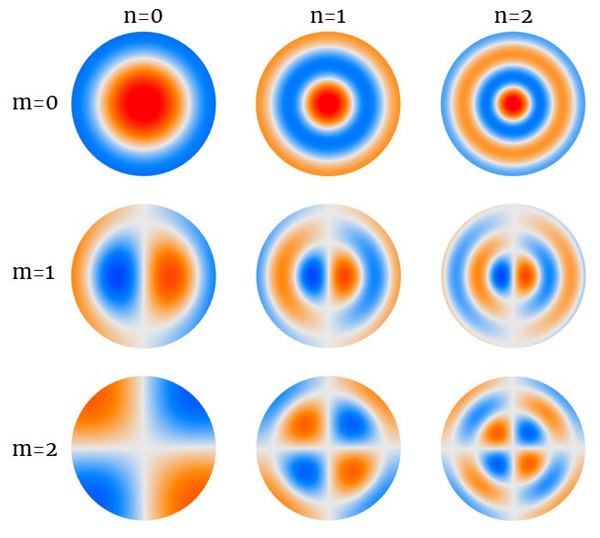
First modes of vibration of a free circular panel
The vibrations of thick plates are described by the oscillations of the three quantities that describe the current configuration: $$W$$, $$\psi_1$$, $$\psi_2$$. As a result, to each natural frequency $$f_{mn}$$ correspond 3 wave numbers $$k_1$$, $$k_2$$, $$k_3$$. There exists a coupling between flexural modes, thickness-shear modes and thickness-twist modes. Another interesting phenomenon is the existence of a cut-off frequency that separates the low-frequency modes from the high-frequency modes, giving rise to distinct mode shapes.
Experiments
The theory was tested by confronting it to experimental results. The deflections were measured for a simply-supported circular inflatable panel with uniform vertical load.
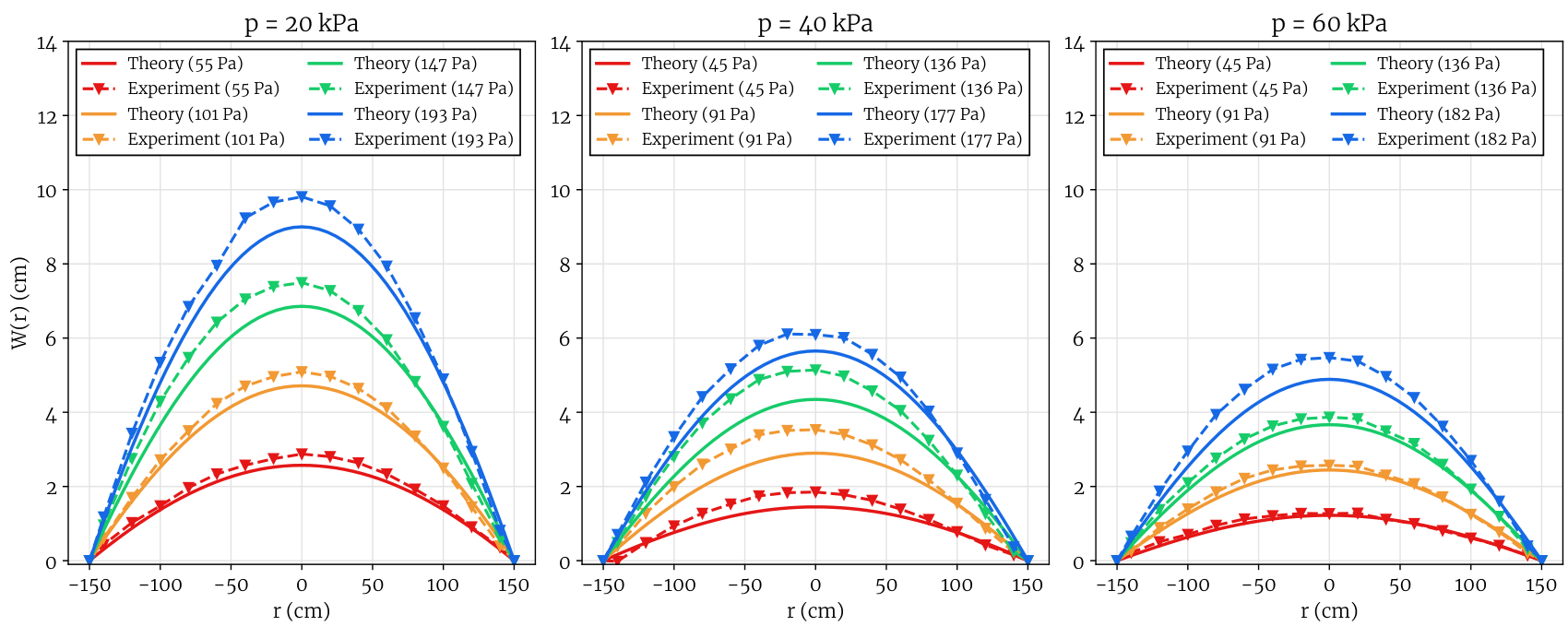
Experimental deflection profiles (--) compared to the analytical solution (—) for several uniform vertical loads.
Finite element
The nonlinear expression of the PVP can be discretized to create nonlinear finite elements dedicated to modeling inflatable panels using flat elements.